Space Age hand tools in the Maker Age
tl;dr How I 3D printed a Volkswagen hand tool from a 1960 blueprint, realizing a half-century-old vision of locally-made equipment.
I recently got inspired by a little side project while working on my van. I had to rebuild the power steering pump, which involves pulling the old rubber seal out of the pump.
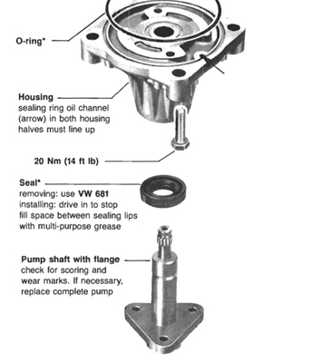
I’d never used a seal puller (a commonly available shop tool) before, so I did a little digging on what exactly the VW 681 was. That led me to this 2007 blog post wherein the author references Volkswagen’s Workshop Equipment for Local Manufacture. As it turns out, back in the 1950s and 1960s, Volkswagen intended for a whole class of tools to be made local to the repair shop, presumably using other common tools and processes. The blog author goes on to explain how they found the blueprint for VW 681 and was able to fashion it fairly handily out of steel bar stock (essentially scrap metal).
It occurred to me that I could use the blueprint to create a CAD drawing and probably 3D print the tool. Though originally intended to be made of steel, the way that the tool is used stresses it edgewise. A 3D printed plastic like ABS would probably be strong enough, at least as strong as the rubber seal, and maybe even less likely to mar the steel surface of the pump from which the seal was being removed.
Using the image from the blog post, plus the comment that the author used 1/8" bar stock, I figured I could draw the profile of the tool, extrude it to 1/8", and try 3D printing. Along the way, I got a lot better at a few things:
- Drawing complicated 2D shapes
- Learning the hard way about cross-section symbology
- Getting creative in order to create non-uniform extrusion depths
- Modifying the model slightly to fit my 3D printer
Read on for more details!
I have been using OpenSCAD a lot lately as my CAD tool of choice. It’s markup-based, meaning that you design visual models using text-based programming rather than GUI tools. This appeals to my programmer mindset, and especially in keeping my hands on the keyboard rather than a lot of back-and-forth with the mouse.
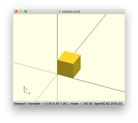
As an example, to create a cube of unit size in 3D x/y/z space, you’d write the following:
cube([1,1,1]);
Hit Save and the result looks like this:
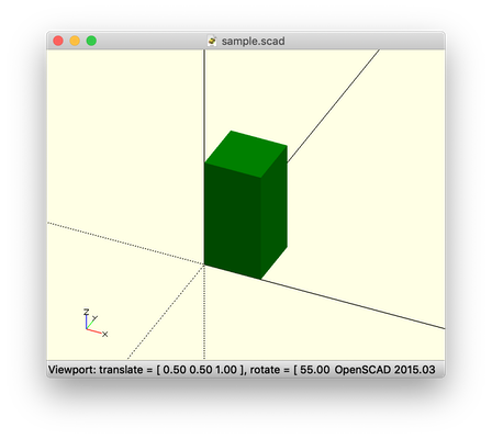
Want to make it taller and also green instead of the default of yellow? Make the z index greater and assign an explicit color:
color("green") cube([1,1,2]);
Combine simple shapes like cubes and cylinders with placement and orientation commands like translate and rotate and you have more complex creations.
Add in some boolean logic like intersection and difference and you can start to show only where shapes intersect, or to subtract shapes from other shapes in order to carve things out.
And one other feature of OpenSCAD that I used for this project was 2D shapes to create the profile of the tool much like the blueprint. It was complicated, and this part was probably more easily done with a traditional drafting tool, but I wanted to get better at OpenSCAD in particular. Eventually I was writing code like this to get things together:
a=acos((c2.y-c1.y)/(r1+r2)); // fillet tangent angle
t2=sin(a)*r2; // tangent point of c2 & extension body

difference() { // extension top fillet
    translate([0,c2.y]) polygon([
        [0,-r2],
        [-r2+t2,-r2],
        [0,0]
    ]);
    translate(c2) circle(r=4);
}
In OpenSCAD, often it’s useful to make use of programming-style variables if you are going to reuse values frequently, or for more clarity and labeling in comments for future reference.
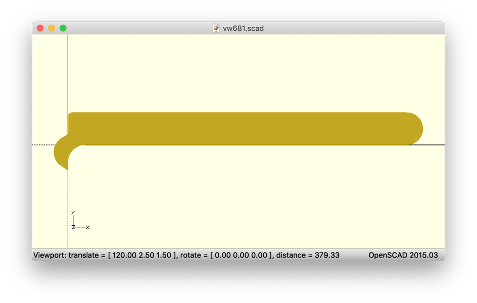
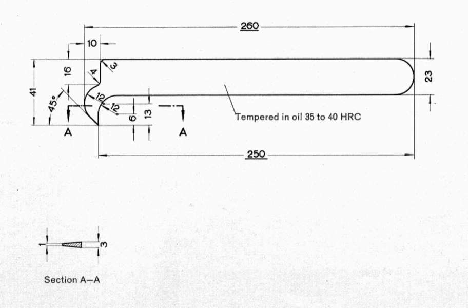
In the end, I got a good-looking side profile of the tool!
Including a pretty complicated point area:
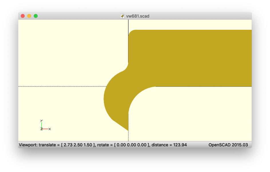
This took about 75 lines of code. And I was able to trivially extrude it to 1/8" thickness with one more line:
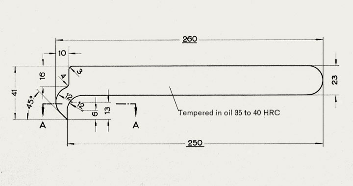
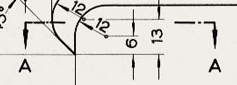
Something kept bothering about the blueprint snippet, though, and those A markings.
I wanted to get back to the original blueprint and see what I could learn. I had to do a bit more digging to find working links, but eventually happened upon the Obsolete Air-Cooled Documentation Project. While my 1985 van isn’t air-cooled but rather water-cooled like more modern vehicles, tools like VW 681 originated back in the bug and minibus days and apparently were still in common use later on, as evidenced by my Bentley manual.
I was able to download a PDF version of the tool catalog and get at the full blueprint.
Ah! I was both relieved and dismayed to learn that A—A is a cross-section detail. The dismaying part is the complexity of extruding my shape at a variable thickness like that. I had no idea how I was going to do this. Extruding at a fixed thickness is trivial:
linear_extrude(height=3) <2D shape instructions>;
(3 units, i.e. millimeters, is 1/8")
But varying the height value isn’t possible. I needed to tell OpenSCAD to vary the z value at various, specific points along the y direction.
I thought a bit about this, reread the manual, and checked for open feature requests and community-made plugins. Nothing of use.
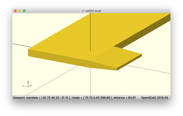
Then it occurred to me that I could design simple solids of the right thickness and intersect the tool profile with them to define the thicknesses.
First, I took all of my 2D code and put it into a function, or module, as OpenSCAD calls them.
module tool_outline() { <2D shape instructions> }
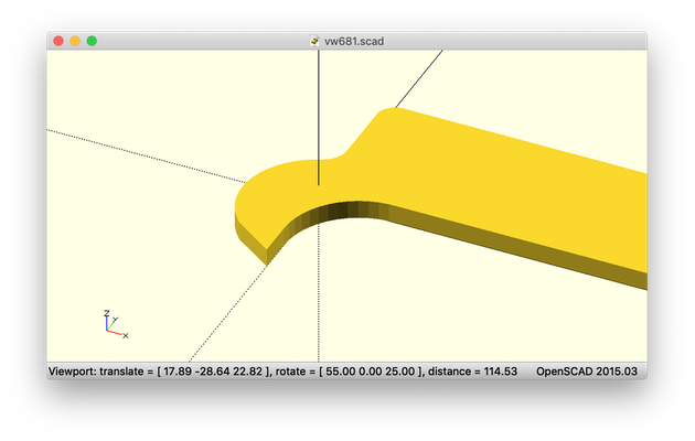
Then I defined two solids. The first covers the uniform 3mm thickness of the handle and main tool head. And the second uses a simple trapezoid that defines the cross-section and extrudes it in the x direction.
polygon([[0,1],[0,2],[13,3],[13,0]]);
Together, the intersection solids look like this:
Using intersection, I can call my 2D tool profile function twice, once to intersect with each solid, making two parts of the tool which sit next to each other and look like one piece.
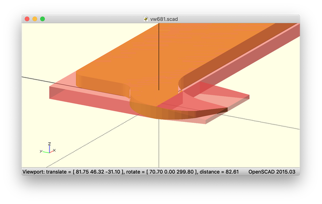
Hide the intersection solids and there we have it!
OpenSCAD allows you to easily export models to the .stl format, which happens to be what most 3D printers need. Once I got to trying to fit the model on my Lulzbot Mini 2 3D printer, though, I realized that even diagonally, the handle was too long. But I didn’t need the full length to make the tool usable, so I adapted that out into a variable and adjusted it for my needs.
handle_length=175; // full-size: 250
Then it fit just fine on my printer.
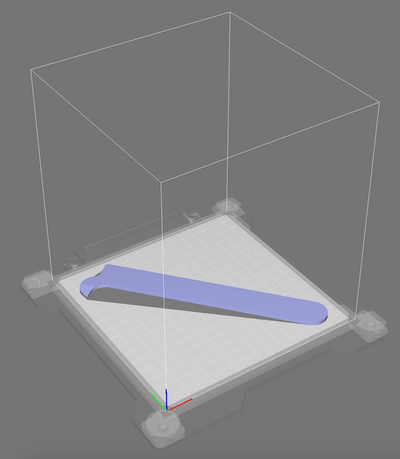
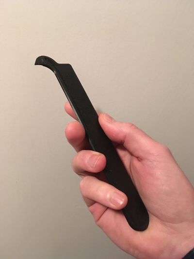
The job took about fifteen minutes to print (after hours of CAD work), but finally, at long last, I held a 1960-designed shop tool in my hand and never even had to leave my desk. Amazing.
It was super inspiring to me to realize this half-century-old vision of tools made at the edge, in local workspaces. I’m sure that the originators never thought such a process would be possible.
So, yeah, I could have gone and spent $10 on a standard seal puller that may have done the job, but getting way better at CAD and the design of physical things was a fun little yak shave or, as we used to like to call them at Mapbox, side quest. Plus, it was fascinating to me to realize in 2019 the vision of a 1960 VW engineer using a process that would have seemed—and truly is—space-age.